
Approach Angle in Stereotaxic Surgery

Neuroscientists have long been aware of a compromise in stereotaxic surgery. It was explained to me in graduate school in the 1960’s. Conventionally, every surgery in both the control group and the experimental group is done from the same angle, usually straight down, but sometimes, to avoid a given structure, such as the midline arteries, all are done from a preset angle. Thus, all commercial small animal stereotaxic instruments have swivels and tilts to allow complex angles. However, placing the probe tip in the target structure from an angled position usually requires a pilot study. So the most reliable way to hit the target is straight down, matching the atlas, or all surgeries done at the same probe angle. Successfully reaching the target is a high priority.
The Stereotaxic Confound
However, doing every surgery from the same path of approach means that there is usually confound, that is, both the action at target, and the path of approach vary together. For example, if the experiment involves making an injection in the hypothalamus, deep in brain, the needle passes through several structures above the target. Some fluid leaks out on the way down. When fluid is forced out, it flows up along the cannula track as the path of least resistance. When the needle is withdrawn, injected fluid follows it back out. To confound is that one cannot know whether fluid injected at the target, or somewhere above it, then caused the effect on the dependent variable later. A specific case: after injecting HRP, then staining for it later, the experimenter will always see a sphere of stain color at the target, with a narrowing line of stain color going all the way up to cortex surface. HRP is thus present both at the target site, and along that needle track. Suppose cells are stained in the amygdala, far from the injection site. The experimenter would like to say that was because axons from that region picked up HRP at the target site, and transported it back. But he cannot rule out that the axons from those amygdala cells instead picked up HRP at any point along the needle track. If the needle track is always through the same structures, the experimenter cannot be sure.
Similarly, a lesion study always involves electrode track damage along the path down to the target. Even with controls operated on and needle inserted, but not lesioned, the researcher cannot be sure that the electrode damage to cells, axons, or blood vessels in the path of approach does not contribute to the lesion effect on the dependent variable.
A Different Angle
The ideal solution to this conflict of positional accuracy vs. interpretability would be to do every surgery from a different angle of approach, and hit the same target each time. If an action at the target then has the same effect in all animals where the target was reached, the path of approach cannot have anything to do with that result; the path was different for each of the effective injections.
A Very Accurate Method
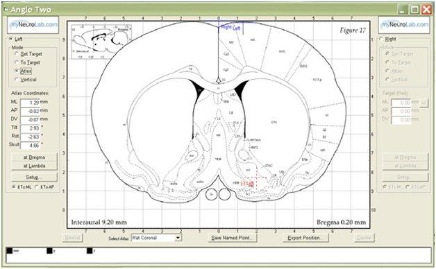
Fortunately, in this computer age, this method is no longer too difficult to be practical. In fact, it can be easy if the stereotaxic instrument is fitted with linear encoders on each of the 3 linear axes, and rotary encoders on both rotation axes. A computer can instantly do the complex 3 D trigonometry if the tilted and rotated probe is touched down at Bregma, and can then provide the distance from the target along each of the 3 linear axes, given the tilt and rotation present.
If the probe tip is also touched at Lambda, the computer can calculate the head tilt and correct for it, no need to adjust the head by trial and error to the “skull flat” reference position.
The use of encoders makes this method very accurate. Encoders are recognized as more accurate than stepper motors, since a count occurs only when the read head actually has moved over a laser engraved graduation mark. A stepper motor selected and powered to be quiet and smooth can occasionally miss a movement pulse if resistance varies over the range, or an end of range stop is encountered. Because there is no feedback, the count is made when the step voltage is applied, and the electronics is not informed the directed movement did not actually occur. A missed step means the instrument will remain inaccurate on its position coordinate until re-zeroed.
An encoder is non-contact, zero force optical reading, and very unlikely to generate a count when a movement did not occur, or fail to generate a count when one did, if the read head and scale are aligned and clean. If they are not aligned and clean, the error is generally going to be more obvious than one missed count.
Avoiding the confound by varying the angle of approach is better science, yielding more interpretable data. Avoiding the trial and error process of finding the skull flat position reduces surgery time, and improves accuracy.
About the presenter
Charles Scouten acquired his Ph.D from SUNY Binghamton in 1980 with a dissertation entitled “Location of Neurons Mediating Androgen’s effect on Copulation, Urine Marking, and Body Weight”.
Related Content


Leica Biosystems Knowledge Pathway content is subject to the Leica Biosystems website terms of use, available at: Legal Notice. The content, including webinars, training presentations and related materials is intended to provide general information regarding particular subjects of interest to health care professionals and is not intended to be, and should not be construed as, medical, regulatory or legal advice. The views and opinions expressed in any third-party content reflect the personal views and opinions of the speaker(s)/author(s) and do not necessarily represent or reflect the views or opinions of Leica Biosystems, its employees or agents. Any links contained in the content which provides access to third party resources or content is provided for convenience only.
For the use of any product, the applicable product documentation, including information guides, inserts and operation manuals should be consulted.
Copyright © 2026 Leica Biosystems division of Leica Microsystems, Inc. and its Leica Biosystems affiliates. All rights reserved. LEICA and the Leica Logo are registered trademarks of Leica Microsystems IR GmbH.